 |
 |
| View previous topic :: View next topic |
| Author |
Message |
viki2000
Joined: 08 May 2013
Posts: 233


|
| Reconstruction Filter |
 Posted: Fri Jan 27, 2017 2:20 am Posted: Fri Jan 27, 2017 2:20 am |
 |
|
I need to generate a rectified sinewave 1Vpp 100Hz using MCP4725 and lookup table.
The PIC is PIC16F1825 working at 32MHz.
The values for lookup table we can generate either using next page:
http://www.daycounter.com/Calculators/Sine-Generator-Calculator.phtml
or, as I prefer, using next software Smart Sine:
http://tahmidmc.blogspot.de/2012/10/smart-sine-software-to-generate-sine.html
I used next code:
| Code: | #include <16F1825.h>
#fuses NOFCMEN, NOIESO, NOCLKOUT, BROWNOUT, NOCPD, NOPROTECT, NOMCLR, NOPUT, NOWDT, INTRC_IO
#fuses NOLVP, NODEBUG, BORV19, NOSTVREN, PLL, NOWRT
#use delay(clock=32M)
#use I2C(MASTER, scl=PIN_C0, sda=PIN_C1, FORCE_HW, FAST=600000)
CONST unsigned long SINE_WAVE[100] = {0, 26, 51, 77, 103, 128, 153, 179, 204, 228, 253, 277,
301, 325, 349, 372, 395, 417, 439, 460, 481, 502, 522, 542, 561, 579, 597, 614, 631, 647,
663, 677, 692, 705, 718, 730, 741, 752, 761, 771, 779, 786, 793, 799, 804, 809, 813, 815,
817, 819, 819, 819, 817, 815, 813, 809, 804, 799, 793, 786, 779, 771, 761, 752, 741, 730, 718,
705, 692, 677, 663, 647, 631, 614, 597, 579, 561, 542, 522, 502, 481, 460, 439, 417, 395, 372,
349, 325, 301, 277, 253, 228, 204, 179, 153, 128, 103, 77, 51, 26};
void dac_i2c(unsigned int16 sample){
i2c_start(); // Start
i2c_write(0b11001000); // Device address
i2c_write(0b1000000); // Internal Device address
i2c_write((sample & 0xFF0) >> 4); // Upper data bits (D11.D10.D9.D8.D7.D6.D5.D4)
i2c_write((sample & 0xF) << 4); // Lower data bits (D3.D2.D1.D0)
i2c_stop(); // Stop
}
void main() {
setup_adc(ADC_OFF);
unsigned long int i=0;
disable_interrupts(GLOBAL);
while(TRUE){
if (i++ == 99)
i = 0;
#asm
nop
nop
nop
nop
nop
nop
nop
nop
nop
nop
nop
nop
nop
nop
nop
nop
nop
nop
nop
nop
nop
nop
nop
nop
nop
nop
#endasm
dac_i2c(SINE_WAVE[i]);
}
} |
Here is the circuit used:
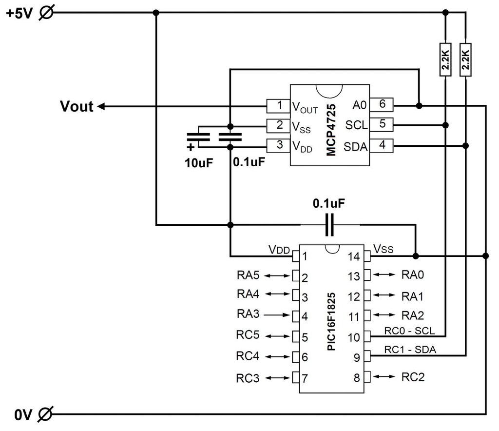
In order to achieve 100Hz I tweak the code in the next ways:
- Either I introduce some delays as “nop” above.
I have tried with “delay_us();” but is not so precise.
- Or I play with I2C bus speed.
In this case I set it to 600kHz.
- Both above, as I did it.
Here is the waveform output:
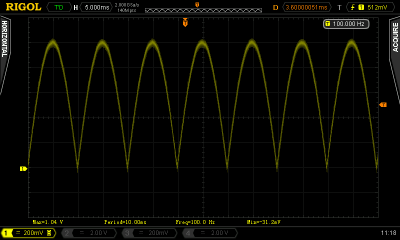
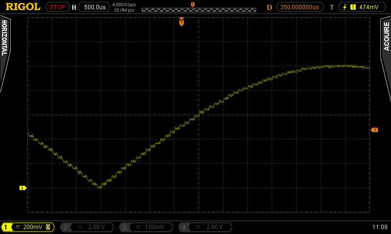
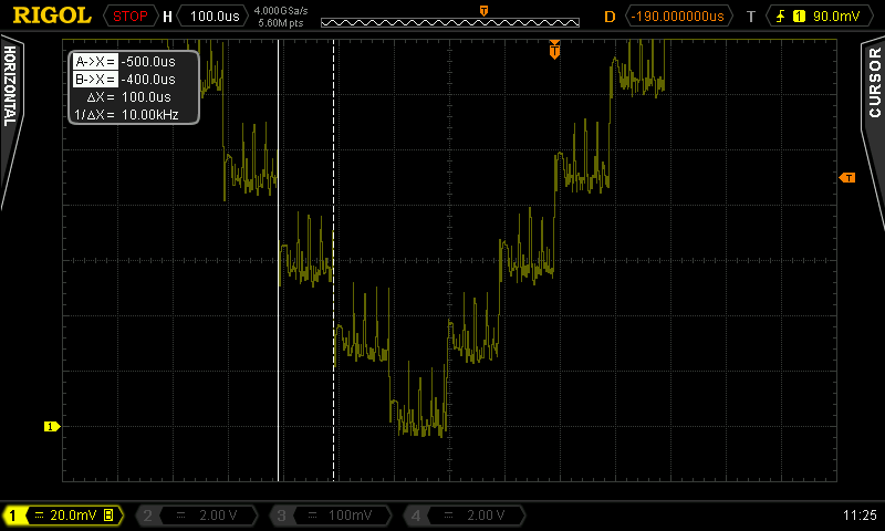
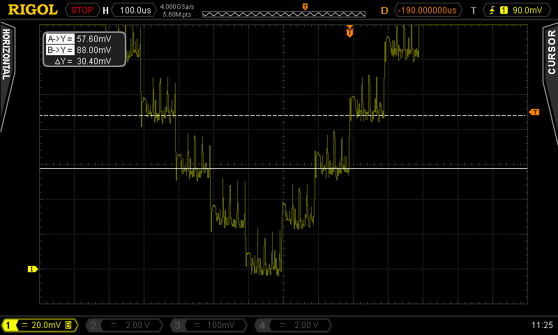
Each step is 30mV and 100us.
With +5V dc I can get 5V/4096=1.22mV.
I would be happy to have a step like that.
That would imply for my 1Vpp 1V/1.22mV=819 levels, steps.
I cannot get the lookup table so high due to I2C speed and PIC speed limitations.
And that would be the same if I use a trigonometric function instead of lookup table.
Three is some noise seen on oscilloscope on each step. I do not know from where is coming, can be the scope probes or the breadboard used for tests or the circuit itself.
My problem is that I would like to emulate the sinewave as good as possible.
One way would be to enlarge the lookup table or to use a trigonometric function, but then how do I increase the I2C speed?
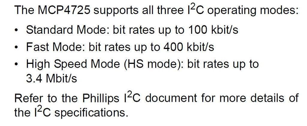
In the manual of the MCP4725 is written that can work also in High-Speed Mode 3.4Mbps.
Why am I limited at 1.9MHz? Is it due to PIC?
I was also thinking that reconstruction filter may help.
What kind of filter do you suggest? |
|
 |
Ttelmah
Joined: 11 Mar 2010
Posts: 19538


|
|
 Posted: Fri Jan 27, 2017 6:09 am Posted: Fri Jan 27, 2017 6:09 am |
 |
|
Your basic synthesis is fine. It's just the numbers being used that are wrong.
What you have is the +ve half cycles of a sine wave, going from 0 to 1v being repeated. Your sine wave needs to have your existing data, halved in amplitude, but added to your half level output value, for half a cycle, then subtracted from the same value for the next half cycle.
The step size will then be half what it currently is.
The glitches are almost certainly digital noise, which means you need to improve layout/grounding.
Then I2C above 400KHz, really requires an active terminator. You are 'pushing it' at 600K. Your 'nop' section is pointless. This is why CCS has 'delay_cycles'.
Then just add a little analog filtering. |
|
 |
asmboy
Joined: 20 Nov 2007
Posts: 2128
Location: albany ny


|
|
 Posted: Fri Jan 27, 2017 10:36 am Posted: Fri Jan 27, 2017 10:36 am |
 |
|
a 45 point "1 degree"
or 90 point 1/2 degree
lookup table would do nice enough sine waves
with some analog magic:
| Code: |
loop{
positivecycle{
count up the table then back down
}
negativecycle{
switch on inverter
positive cycle()
off inverter
}
} // loop end |
|
|
 |
temtronic
Joined: 01 Jul 2010
Posts: 9243
Location: Greensville,Ontario


|
|
 Posted: Fri Jan 27, 2017 2:27 pm Posted: Fri Jan 27, 2017 2:27 pm |
 |
|
| Don Lancaster once wrote about 'Magic Sinewaves', that HAS to be on the Net 'somewhere'..... |
|
 |
viki2000
Joined: 08 May 2013
Posts: 233


|
|
 Posted: Mon Jan 30, 2017 7:17 am Posted: Mon Jan 30, 2017 7:17 am |
 |
|
@Ttelmah
I have read your recommendations several times, but I am not sure I understand them all as you meant.
Especially this:
| Quote: | | “What you have is the +ve half cycles of a sine wave, going from 0 to 1v being repeated. Your sine wave needs to have your existing data, halved in amplitude, but added to your half level output value, for half a cycle, then subtracted from the same value for the next half cycle.“ |
Could you please detail that with more words or perhaps an example?
In my words, If I understand right is next: looking at the waveform as picture, we can notice that is symmetrically constructed: from 0 to 90° (0 to PI/2) is the same as from 90° to 180° (from PI/2 to PI), it is mirrored horizontally. We can see that also by looking at the numbers in the look-up table.
If I understand right, you tell me to have in the table only the numbers from 0 to 90°, but the same table size, with the same number of points, of course different numbers and then the distance between numbers/sine points becomes smaller and then to use a simple arithmetical calculation to generate the second part of the sine-wave from 90° to 180°.
Something like that?
| Code: | #include <16F1825.h>
#fuses NOFCMEN ,NOIESO, NOCLKOUT, BROWNOUT, NOCPD, NOPROTECT, NOMCLR, NOPUT, NOWDT, INTRC_IO
#fuses NOLVP, NODEBUG, BORV19, NOSTVREN, PLL, NOWRT
#use delay(clock=32M)
#use I2C(MASTER, scl=PIN_C0, sda=PIN_C1, FORCE_HW, FAST=1900000)
CONST unsigned long SINE_WAVE[170] = {0, 8, 15, 23, 30, 38, 45, 53, 60, 68, 76, 83, 91, 98, 106, 113, 121, 128, 136, 143, 150, 158, 165, 173, 180, 188, 195, 202, 210, 217, 224, 231, 239, 246, 253, 260, 267, 275, 282, 289, 296, 303, 310, 317, 324, 331, 338, 345, 351, 358, 365, 372, 379, 385, 392, 399, 405, 412, 418, 425, 431, 438, 444, 450, 457, 463, 469, 475, 481, 487, 494, 500, 506, 511, 517, 523, 529, 535, 540, 546, 552, 557, 563, 568, 574, 579, 584, 590, 595, 600, 605, 610, 615, 620, 625, 630, 635, 640, 644, 649, 654, 658, 663, 667, 671, 676, 680, 684, 688, 692, 696, 700, 704, 708, 712, 715, 719, 723, 726, 730, 733, 736, 740, 743, 746, 749, 752, 755, 758, 761, 764, 766, 769, 772, 774, 777, 779, 781, 783, 786, 788, 790, 792, 794, 795, 797, 799, 801, 802, 804, 805, 806, 808, 809, 810, 811, 812, 813, 814, 815, 816, 816, 817, 817, 818, 818, 818, 819, 819, 819};
void dac_i2c(unsigned int16 sample){
i2c_start();
i2c_write(0b11001000); // Device address
i2c_write(0b1000000); // Internal Device address
i2c_write((sample & 0xFF0) >> 4); // Upper data bits (D11.D10.D9.D8.D7.D6.D5.D4)
i2c_write((sample & 0xF) << 4); //lower bits
i2c_stop(); // Stop
}
void main() {
setup_adc(ADC_OFF);
unsigned long int i=0;
disable_interrupts(GLOBAL);
while(TRUE){
while (i< 169){
i++;
delay_cycles (33);
dac_i2c(SINE_WAVE[i]);
}
while (i>0){
i--;
delay_cycles (33);
dac_i2c(SINE_WAVE[i]);
}
}
} |
That would be nice, but takes double time and the end frequency is 50Hz, so something is wrong.
Either I did not understand you properly or it is not possible what you suggested.
I would like to make in half the step using the same look-up table size without reducing the output frequency in half.
Can you clarify it for me please?
| Quote: | | “Then I2C above 400KHz, really requires an active terminator. You are 'pushing it' at 600K” |
I am using only pull-up resistors because is written in the datasheet of MCP4725 like that.
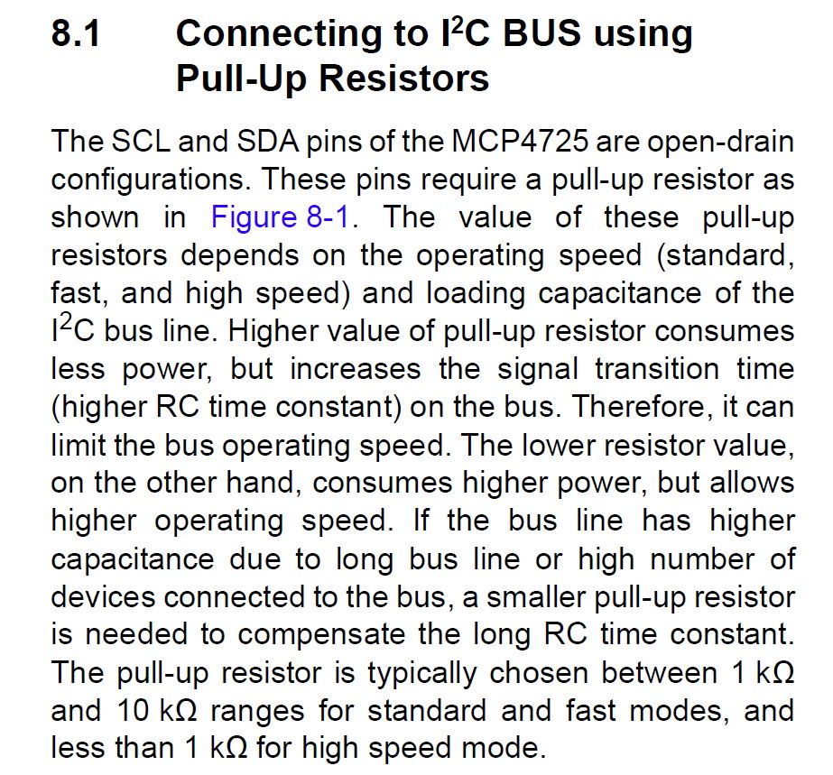
It is true that they recommend only 3 modes: 100KHz, 400KHz and 3.4Mhz and I used 600KHz.
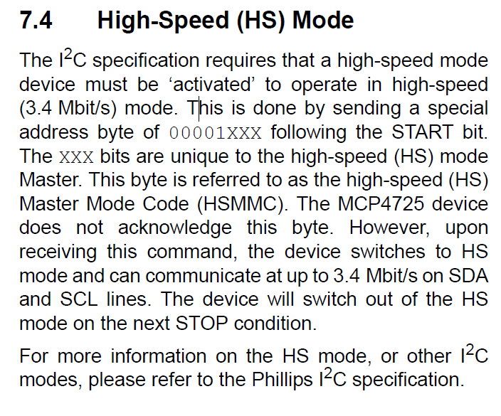
In fact it works up to 1.9MHz and I wanted higher, but above 2MHz stops.
Then reading the datasheet one more time I realized I must use a special command mode for high-speed, but I did not try it yet:
| Quote: | | “Your 'nop' section is pointless. This is why CCS has 'delay_cycles'.” |
You are right, I really forgot about it. I included them now instead of nops.
| Quote: | | “Then just add a little analog filtering.” |
I think that is my initial question. What kind of filter?
Do you mean a simple RC or RLC filter? Or an active filter as low pass Sallen Key?
I have tried a Sallen Key and I get a full sine wave with DC offset, only positive values. I need a full rectified wave and not a full wave. Maybe I need something as an integrator or a precise rectifier with OP AMP, no idea yet. Important is that output wave to touch 0V, no offset and to be rectified full sine wave 1Vpp 100Hz.
@asmboy
I do not have negative cycles, because I do not want to generate a full sine wave.
I need to generate a full rectified sine wave which touches 0V.
Then it would be only half of your pseudo code and I guess is similar with what Ttelmah suggested above or similar with my last code example.
But my question is about the filter, the reconstruction filter and eventually how to increase the I2C speed if it is possible based on given PIC16F1825. |
|
 |
Ttelmah
Joined: 11 Mar 2010
Posts: 19538


|
|
 Posted: Mon Jan 30, 2017 7:54 am Posted: Mon Jan 30, 2017 7:54 am |
 |
|
You are actually generating this:
<http://www.kpap.net/notes/item.php?id=RMSSinusoidSegments>
Look at the second diagram down the page. You have the values for a half wave, going from 0 to 1v, and are repeating these.
To generate a full wave the same amplitude, you need to halve the amplitude of your waveform, then offset these values 'up' by half a volt (so these now go from half a volt to one volt), for one half cyle, then use the same value again, but now take them away from the half volt value.
On the pull-ups, do what they say and read the high speed mode documentation. HS mode, actually requires both devices to support it, and has a current source pull-up (not a simple resistor).
<https://www.i2c-bus.org/highspeed/>
The PIC actually has sufficient drive to operate high speed busses up to perhaps 1.5Mb/s, but to get reliability over 400Kb/sec, you do need the active pull-ups.
You also have to re-program the I2C interface to alter how clock stretching is handled, but this works OK with a PIC as master. |
|
 |
viki2000
Joined: 08 May 2013
Posts: 233


|
|
 Posted: Mon Jan 30, 2017 8:30 am Posted: Mon Jan 30, 2017 8:30 am |
 |
|
This is where I do understand what do you mean:
| Quote: | To generate a full wave the same amplitude, you need to halve the amplitude of your waveform, then offset these values 'up' by half a volt (so these now go from half a volt to one volt), for one half cyle, then use the same value again, but now take them away from the half volt value.
|
You point to this waveform:

That is exactly what I want.
That is also in my first oscilloscope screenshot above. That is what I need: a full rectified wave. I do not need a full sine wave.
It seems that you always point to a full sine wave. Or do I understand you wrong? |
|
 |
Ttelmah
Joined: 11 Mar 2010
Posts: 19538


|
|
 Posted: Mon Jan 30, 2017 9:08 am Posted: Mon Jan 30, 2017 9:08 am |
 |
|
OK. I couldn't see why anyone would want to synthesise a rectified waveform. Everything 'using' synthesised waveforms normally want a full wave.
In which case your synthesis is fine, so just add a low pass filter to get rid of the HF. |
|
 |
viki2000
Joined: 08 May 2013
Posts: 233


|
|
 Posted: Mon Jan 30, 2017 9:38 am Posted: Mon Jan 30, 2017 9:38 am |
 |
|
I wanted a smaller step size. I had in mind either a good reconstruction filter or to enlarge the lookup table, but that would imply higher speed on I2C.
From here all my questions.
I have tried simple low pass RC filter with R=1K and C=150nF.
The improvement is minimal, almost not observable.
Then I tried a 2 poles low pass Sallen key filter (http://www.calculatoredge.com/electronics/sk%20low%20pass.htm) with Ra=Rb=24K and Ca=10nF and Cb=4.7nF, one after another and works better, still not good enough.
I can provide oscilloscope screenshots with the real device, because simulation software is nice but do not reflect the reality always.
I have 170 points in my look-up table. It should be enough.
For example here he has less points (only 50) and higher frequency:
http://www.romanblack.com/onesec/Sine1kHz.htm
and he uses only RC or RLC filters.
He is then speaking about “natural sampling” instead of “regular sampling” and with that “natural sampling” he says reduces the THD with practically zero 2nd harmonic distortion.
I do not understand how he calculated the numbers in the lookup table to achieve that.
Do you have any idea how to generate the lookup table numbers for any given sine-wave in order to achieve that? If you know how, can you explain it with the waveform above 100Hz full rectified sine? |
|
 |
RF_Developer
Joined: 07 Feb 2011
Posts: 839


|
|
 Posted: Mon Jan 30, 2017 11:28 am Posted: Mon Jan 30, 2017 11:28 am |
 |
|
I'm with Ttelmah in not understanding why you need a rectified sine wave. It creates a lot of problems, and I can see almost no applications where it would be useful.
To synthesize a sine wave, recitfied or ordinary, you only need one quadrant of value - a quarter of a full sine wave, generally the first. The other three can very easily be produced by reading out the first quadrant values in reverse order and/or making them negative.
In your case all you need to do is start at the first point, read out one by one till the end of the first quadrant, then go back again, over and over.
If speed is what you are worried about, it would be best to use a pointer to access the table, incrementing it in the first quadrant, then decrementing it for the second. This saves the overhead that is associated with indexing into arrays.
As to improving the quality of the output; your rectified wave causes a bit of a problem. In the eaxmple you've just given, the RC filter is almost certainly (I've not run the numbers...) arranged to filter out most frequencies above 1kHz, including the second harmonic. This is okay for a fixed frequency, but is no good in the general case in which most DACs work, i.e. with arbitrary waveforms. You might think you've only got 100Hz to deal with, but in fact your rectification means that there is massive amount of harmonics in your desired signal, especially second.
Also, such a filter, as can be seen in that example, has considerable delay, making timing/phase control difficult.
I do not, off hand, know the harmonic/spectral content of a rectified sine wave, but its going to be "fun", to say the least. If you filter as aggressively as in that example, i.e. filtering out everything except the fundamental, then that's what you'll end up with: a sine wave at 100Hz! A typical reconstruction filter for general use is usually arranged to filter out every thing above and including the sampling frequency, i.e. your DAC update frequency, leaving the desired waveshape pretty much intact. Even with a pure nyquist reconstruction filter, i.e. one that cuts out everything above fsamp/2, which is really not practical, your signal will not get down to zero. That null point will get somewhat flattened out.
So, it comes down to why you need this easy to generate, but rather unusual signal, and to what the signal purity requirement really is. Do you have any defined requirements? If not, then you probably don't need it to be all that good, and what you have may met you needs. |
|
 |
viki2000
Joined: 08 May 2013
Posts: 233


|
|
 Posted: Tue Jan 31, 2017 2:22 am Posted: Tue Jan 31, 2017 2:22 am |
 |
|
@RF_Developer
Thank you for your thoughts.
I will try to answer to your questions/suggestions
| Quote: | | “I'm with Ttelmah in not understanding why you need a rectified sine wave. It creates a lot of problems, and I can see almost no applications where it would be useful.“ |
I have my itsy bitsy tiny box, just to make fun of my request.
I am aware that creates problems compared with a normal sinewave.
Application? It supposed to be (in future) a possible portable tester operated from batteries, nothing very sophisticated for commercial use with many approvals/certifications, but only for in house testing.
That box will test an existing product/device inserted in a slot/connector of the tester. The device to be tested, in the real application, is connected to mains after a rectifier bridge and detects when the rectified sine-wave touches 0V and measures also the voltage with an ADC 8bits. When will be tested with that portable tester, I should provide/simulate the full rectified sine-wave (as good as possible – defined below) which is seen by the device in the real application. That is all.
| Quote: |
“To synthesize a sine wave, recitfied or ordinary, you only need one quadrant of value - a quarter of a full sine wave, generally the first. The other three can very easily be produced by reading out the first quadrant values in reverse order and/or making them negative.
In your case all you need to do is start at the first point, read out one by one till the end of the first quadrant, then go back again, over and over.
If speed is what you are worried about, it would be best to use a pointer to access the table, incrementing it in the first quadrant, then decrementing it for the second. This saves the overhead that is associated with indexing into arrays.” |
I thought I have done that with the code above, one more time here below:
| Code: | #include <16F1825.h>
#fuses NOFCMEN ,NOIESO, NOCLKOUT, BROWNOUT, NOCPD, NOPROTECT, NOMCLR, NOPUT, NOWDT, INTRC_IO
#fuses NOLVP, NODEBUG, BORV19, NOSTVREN, PLL, NOWRT
#use delay(clock=32M)
#use I2C(MASTER, scl=PIN_C0, sda=PIN_C1, FORCE_HW, FAST=1900000)
CONST unsigned long SINE_WAVE[85] = { 0, 15, 30, 45, 60, 76, 91, 106, 121, 136, 150, 165, 180, 195, 210, 224, 239, 253, 267, 282, 296, 310, 324, 338, 351, 365, 379, 392, 405, 418, 431, 444, 457, 469, 481, 494, 506, 517, 529, 540, 552, 563, 574, 584, 595, 605, 615, 625, 635, 644, 654, 663, 671, 680, 688, 696, 704, 712, 719, 726, 733, 740, 746, 752, 758, 764, 769, 774, 779, 783, 788, 792, 795, 799, 802, 805, 808, 810, 812, 814, 816, 817, 818, 818, 819 };
void dac_i2c(unsigned int16 sample){
i2c_start();
i2c_write(0b11001000); // Device address
i2c_write(0b1000000); // Internal Device address
i2c_write((sample & 0xFF0) >> 4); // Upper data bits (D11.D10.D9.D8.D7.D6.D5.D4)
i2c_write((sample & 0xF) << 4); //lower bits
i2c_stop(); // Stop
}
void main() {
setup_adc(ADC_OFF);
unsigned long int i=0;
disable_interrupts(GLOBAL);
while(TRUE){
while (i< 84){
i++;
delay_cycles (33);
dac_i2c(SINE_WAVE[i]);
}
while (i>0){
i--;
delay_cycles (33);
dac_i2c(SINE_WAVE[i]);
}
}
} |
| Quote: | “As to improving the quality of the output; your rectified wave causes a bit of a problem. In the eaxmple you've just given, the RC filter is almost certainly (I've not run the numbers...) arranged to filter out most frequencies above 1kHz, including the second harmonic. This is okay for a fixed frequency, but is no good in the general case in which most DACs work, i.e. with arbitrary waveforms. You might think you've only got 100Hz to deal with, but in fact your rectification means that there is massive amount of harmonics in your desired signal, especially second.
Also, such a filter, as can be seen in that example, has considerable delay, making timing/phase control difficult.
I do not, off hand, know the harmonic/spectral content of a rectified sine wave, but its going to be "fun", to say the least. If you filter as aggressively as in that example, i.e. filtering out everything except the fundamental, then that's what you'll end up with: a sine wave at 100Hz! A typical reconstruction filter for general use is usually arranged to filter out every thing above and including the sampling frequency, i.e. your DAC update frequency, leaving the desired waveshape pretty much intact. Even with a pure nyquist reconstruction filter, i.e. one that cuts out everything above fsamp/2, which is really not practical, your signal will not get down to zero. That null point will get somewhat flattened out. “ |
Then, can you suggest a filter, a practical example, with schematic and some values for components?
I have tried an active low pass Sallen Key double pole and I can see some improvement, but I expected more.
| Quote: |
“So, it comes down to why you need this easy to generate, but rather unusual signal, and to what the signal purity requirement really is. Do you have any defined requirements? If not, then you probably don't need it to be all that good, and what you have may met you needs.” |
Why I need it I explained above. Now to parameters of the signal, purity, I do not have too many:
- It should be a rectified sine wave 1Vpp 100Hz
- It must touch 0V line, no dc offset
- It should be as smooth as possible without complicated hardware. The 2 poles low pass Sallen Key seems fine except around 0V point where more noise is detected, which is not good.
- It would be good to cut, get rid of the main harmonics. I can measure the harmonics content if it is needed here for discussions.
- I would like to know and understand what Roman Black says about “natural sampling” that reduces the harmonics, especially the 2nd. How did he choose/calculated the number and how should I apply that to my look-up table?
Coming back to the parameters, related with look-up table size and I2C speed, if Roman Black did it with 50 samples in lookup table, “natural sampling” and an RC or RLC filter with 3-4 poles, all for 1KHz, why should be so difficult for only 100Hz? It is true he generates full sine wave and I need a full rectified, but still the output frequency of the signal is 10 times less.
Before I started the tests with DAC, I imagined that a simple tiny PIC, maybe 10F322 or perhaps 12F would provide enough memory and speed at 16MHz or 32MHz to generate the wave that I want using the classical PWM and a RC multi pole filter, because I wanted all to be very small with only few components, if possible SMD. The 10F322 is SOT-23-6, then RC filters can be done with SMD components, even MCP4725 is SOT-23-6, so I was thinking at a little itsy bitsy tiny PCB….
When I would be satisfied with the step size in height mV and width us?
I had in mind next calculation: I use only 5V as power supply, then MCP4725 is 12bits 4096 points, then for 1V I get 4095/5=819 points, then 5V/4096=1.22mV step size.
For me it would be enough if one step it would be 1.22mV, but that would require 819 points in the lookup table and the I2C speed cannot handle it or maybe combined with internal speed of the PIC.
Any suggestion how to find out what limits me to use a lookup table with 819 points? How to find out if it is I2C, let’s suppose I can make it run at 3.4Mbps, or just the 32MHz PIC speed?
I was thinking that a 819 points look-up table with 1.2mV step size would offer a good enough precision to give up to the reconstruction filter. From here my greed for bigger lookup tables and higher speed. That's why I started to test also with 12bit SPI DAC MCP4921:
http://www.ccsinfo.com/forum/viewtopic.php?t=55924&highlight= |
|
 |
Ttelmah
Joined: 11 Mar 2010
Posts: 19538


|
|
 Posted: Tue Jan 31, 2017 3:34 am Posted: Tue Jan 31, 2017 3:34 am |
 |
|
First thing to comment. If this is meant to simulate something receiving rectified mains, this will _not_ be even remotely close to a pure half sine wave. First, unless a precision rectifier is being used, there will be a glitch at the bottom of the waveforms, from the diode offsets. Then mains itself is full of awful spikes and harmonics. The IEEE specifications define that THD should be less than 5% typically at the entry to the property, but inside the building levels will often be far worse, with other types of interference as well. If you are trying to simulate mains behaviour, you should actually be making the signal more noisy, not less...
Put a scope on the 'real' signal....
On the filter, if you look at your signal, there is a fundamental at perhaps 4* the sample frequency (probably digital noise). Look at how the signal is reconstructed from CD's. The good systems use rejection filters at the harmonics of the sampling frequency, to avoid the sort of problems you are seeing.
However I repeat my comment about solving this 'at source'. It's almost certainly a sign of poor layout, with either a digital ground that is drawing current 'across' a section of analog circuitry, or a digital track passing close to analog without a ground between. It looks as if it occurs for each byte in the transmission, so possibly the ACK bit. |
|
 |
RF_Developer
Joined: 07 Feb 2011
Posts: 839


|
|
 Posted: Tue Jan 31, 2017 4:36 am Posted: Tue Jan 31, 2017 4:36 am |
 |
|
| Quote: | | - It would be good to cut, get rid of the main harmonics. I can measure the harmonics content if it is needed here for discussions. |
As I wrote before, you NEED the harmonics. You MUST have them to produce the waveshape you want.
| Quote: | | - I would like to know and understand what Roman Black says about “natural sampling” that reduces the harmonics, especially the 2nd. How did he choose/calculated the number and how should I apply that to my look-up table? |
I am not sure what he really means by "natural" in this context, but his requirement was rather different: he wanted to produce a high purity sinewave at a fixed frequency. It doesn't matter whether it was 100Hz or 1kHz, or even 100kHz, all are equally "easy" to design practical filters for. As I pointed out before, the key difference is that he wanted to produce a pure sine wave, with as little harmonics, i.e. THD, as practical. To do that, he needed to filter out everything above 1KHz and probably wasn't concerned about the sample rate and digital noise at all, as the filter would clobber that pretty hard. So for that he used a simple two stage RC filter as that was all he needed.
EDITED TO ADD: After reviewing the example, some critical differences emerge. For a start he was using PWM rather than a DAC to produce his signal. Lower component count, as most PICs include a suitable PWM, but requires a filter to get an analogue output. "Natural sampling" is, apparently, a method which allows PWMs to be tweaked for greater analogue signal accuracy, essentially by pre-compensating for inevitable timing shifts. His filter was a three stage RC, apparently a hard low cutoff first stage (i.e. to 1KHz) and to higher frequency stages to reduce the (?50KHz?) PWM sampling frequency. Natural sampling is, if I understand it right, not going to be of use when using a DAC.
You, on the other hand cannot do that, you require to preserve as much of the harmonics as possible in order to acheive your desired waveshape. to do that, you have to adopt the filtering approach that both Ttelmah and I have suggested: you need to try to filter out everything from half the sampling frequency and upwards. This is not "hard", at least its still pretty standard analogue processing, but it is "harder" than the example because his filter cutoff frequency was way below the sampling frequency, and threfore easily filtered out far more of the digital than yours can.
As you can see from the table, the signal changes very quicky near ground: your steps there are fifteen DAC counts, while at the "top" of the signal, they ideally would be less than one count per time step. If you want greater precision, you might think you'd need to go higher sampling rate, but in reality, that probably wouldn't make much difference as there wouldn't be much more information in those large steps, and the top of the waveform would not be any better at all, where its precision is determined by DAC step size, not sampling rate. In any case, there is DAC linearity to consider, which will add distortion to your signal. What I think you need is better filtering, if anything (see below), not higher sampling rate.
Personally, I wouldn't be too fussy about the signal purity. The "test box" application doesn't seem to call for high precision. In any case, with you using Vdd as your DAC reference, any digital noise on the power, and there will be quite a lot, will get through to the output of the DAC. Using a precision reference doesn't jsut give you a more precise output, it can also substantially reduce noise, with good layout and careful choice of components. I nany case, I'd probably just go for a simple RC or single stage active filter (difficult if the required output is true rail-to-rail, as seems to be the case here). |
|
 |
viki2000
Joined: 08 May 2013
Posts: 233


|
|
 Posted: Tue Jan 31, 2017 5:15 am Posted: Tue Jan 31, 2017 5:15 am |
 |
|
@Ttelmah
I understand your explanation about a real mains, but is not important to me now. I would like to emulate nice sine waves without noise. The real device has been tested according with all the necessary IEC norms and EMC Directive by a accredited test house and passed all the requirements. I only want to provide a rectified sine wave to test certain functionality of the device. I need it clean, I do not care about the dirty reality.
One thing for sure, you are right with the noise. I will try to make a proper layout on a test PCB. Right now I do fast tests, in between other tasks when I have time, and I just tested on a simple breadboard, so no wonder of the noise.
@RF_Developer
After a proper circuit layout, I will try once again some simple RC filters as you suggested, maybe 2-3 stages as Roman Black.
As for “natural sampling” I will dig more in his words, where he provided also an example for Excel. The idea is to choose the numbers in the lookup table in such way to get rid of some harmonics, but you say I need them. Well, I can measure them now, then with a filter and then with some “natural sampling” numbers, then I compare and I see the result.
You say | Quote: | | “you need to try to filter out everything from half the sampling frequency and upwards” |
Then, in my table above I have 85 numbers for 0°…90° range. The period of my signal is from 0° to 180°, that would mean 170 numbers/samples. That period corresponds to 100Hz signal, so 10ms.
I have then 170 samples for 10ms, which implies 17Khz sampling rate. Then the low pass filter should be 8.5KHz where I start to cut the higher frequencies.
Is that what you meant?
I will come back after several days, as I am busy now with other tasks. |
|
 |
Ttelmah
Joined: 11 Mar 2010
Posts: 19538


|
|
 Posted: Tue Jan 31, 2017 6:10 am Posted: Tue Jan 31, 2017 6:10 am |
 |
|
| If you look at the spikes, there are two parts to them. The first is overshoot on the DAC itself. The second is three spikes along each 'flat'. Now the latter I suspect good design will largely remove. The former, you may have to improve with filtering. Your filtering should be on the harmonics of the DAC rate, not the waveform rate. (though they are related, the DAC ones are at much higher frequencies). The odd harmonics of the waveform rate must be left largely unfiltered to give the sharp transition at 9v. |
|
 |
|
|
You cannot post new topics in this forum
You cannot reply to topics in this forum
You cannot edit your posts in this forum
You cannot delete your posts in this forum
You cannot vote in polls in this forum
|
Powered by phpBB © 2001, 2005 phpBB Group
|


