 |
 |
| View previous topic :: View next topic |
| Author |
Message |
timtalk
Joined: 14 Oct 2005
Posts: 10


|
| Reading Pin input F628A |
 Posted: Sun Oct 16, 2005 12:02 pm Posted: Sun Oct 16, 2005 12:02 pm |
 |
|
Can someone look at this and see what i'm doing wrong. I'm trying to read pin B1 and determine if it has 5V being applied to it or not. I currently have A1 connected to a momentary switch and the other side of that switch connected to B1. I'm setting A1 high and I would expect that B1 would then indicate high. I'm including the code that i'm using to test this below. FYI i'm using CCS PCM C Compiler, Version 3.190
| Code: |
#include <16F628A.h>
#fuses LP,NOPROTECT,NOWDT,PUT,NOBROWNOUT,NOMCLR,NOLVP
#use fixed_io(A_OUTPUTS=40,41,42,43,46,47)
#byte port_A=5
#use fixed_io(B_OUTPUTS=48,49,50,51,52,53,54,55)
#byte port_B=6
#use delay(clock=32768)
key_read()
{
output_high(PIN_A1);
delay_ms(500);
If(input(PIN_B1))
{
output_high(PIN_B7); // used to indicate that it detected an input
}
}
main()
{
OUTPUT_A(0x00);
OUTPUT_B(0x00);
while(1)
{
key_read();
}
}
|
|
|
 |
jecottrell
Joined: 16 Jan 2005
Posts: 559
Location: Tucson, AZ


|
|
 Posted: Sun Oct 16, 2005 1:55 pm Posted: Sun Oct 16, 2005 1:55 pm |
 |
|
Try this:
| Code: |
/********************************************
This routine will only check for one keypress
********************************************/
#include <16F628A.h>
#fuses LP,NOPROTECT,NOWDT,PUT,NOBROWNOUT,NOMCLR,NOLVP
#use delay(clock=32768)
main() {
output_high(PIN_A1); //only need to set this once
while(1) {
If(input(PIN_B1)) {
delay_ms(50); //short debounce delay
output_high(PIN_B7); // used to indicate that it detected an input
}
}
|
EDIT: You may want to pull B1 down with a 10K resistor and put a current limit resistor (4.7K or so) between A1 and the switch. |
|
 |
drolleman
Guest
|
|
 Posted: Sun Oct 16, 2005 2:21 pm Posted: Sun Oct 16, 2005 2:21 pm |
 |
|
have you got a resistor from input to ground? or is it floating?
if it's floating you will always see logic 1 |
|
 |
PCM programmer
Joined: 06 Sep 2003
Posts: 21708


|
|
 Posted: Sun Oct 16, 2005 2:29 pm Posted: Sun Oct 16, 2005 2:29 pm |
 |
|
| Quote: | | I'm trying to read pin B1 |
Take this line here, and get rid of the magic numbers and put the symbolic names back in.
| Code: | | #use fixed_io(B_OUTPUTS=48,49,50,51,52,53,54,55) |
I submit that when you do this and then look at your complaint
that I've quoted above, you will see the problem. |
|
 |
timtalk
Joined: 14 Oct 2005
Posts: 10


|
|
 Posted: Sun Oct 16, 2005 4:45 pm Posted: Sun Oct 16, 2005 4:45 pm |
 |
|
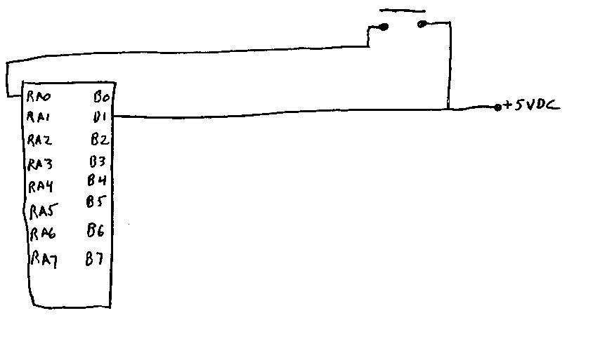
PCM Programmer, I think that i've figured out what you mean. I have to use fast_io and set my tris setting in order for it to work properly. I've managed to get it to work now but it won't work for the keypad setup that I need. I currently have the following connections made

and I have this code
| Code: |
#include <16F628A.h>
#fuses LP,NOPROTECT,NOWDT,PUT,NOBROWNOUT,NOMCLR,NOLVP
#use fast_io(A)
#byte port_A=5
#use fast_io(B)
#byte port_B=6
#use delay(clock=32768)
key_read()
{
output_float(pin_B1);
output_low(pin_A0);
If(!input(PIN_B1))
{
output_high(Pin_B7);
Delay500();
}
Delay500();
Delay500();
Delay500();
}
main()
{
set_tris_a (0x00);
set_tris_b (0x02);
output_A(0x00);
output_B(0x00);
while(1)
{
key_read();
Delay500();
Delay500();
Delay500();
Delay500();
Delay500();
}
} |
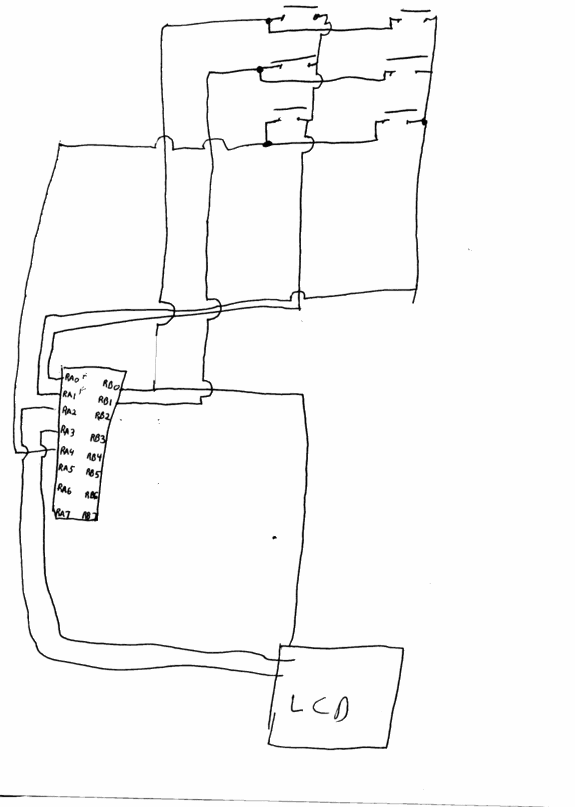
With this setup It does seem to work. The problem is that I need to have my final connections look like below or be similar to them.

can you give me any direction in what I need to change in order for this to work properly? |
|
 |
PCM programmer
Joined: 06 Sep 2003
Posts: 21708


|
|
 Posted: Sun Oct 16, 2005 5:57 pm Posted: Sun Oct 16, 2005 5:57 pm |
 |
|
Well you know, the example that you're following, which is Tip #12
in the Microchip LCD Tips 'n Tricks document, expects you to use a PIC
that has an A/D converter. Your PIC doesn't have one.
http://ww1.microchip.com/downloads/en/DeviceDoc/41261a.pdf
So you've made your project harder than it needs to be, especially
for a beginning project. |
|
 |
timtalk
Joined: 14 Oct 2005
Posts: 10


|
|
 Posted: Sun Oct 16, 2005 6:04 pm Posted: Sun Oct 16, 2005 6:04 pm |
 |
|
| Well I thought I only needed an A/D if I was trying to read a value from a pin. I thought that doing it this way (not using resistors tieing all 6 pins together) would allow a 5V or 0V reading which I thought this pic could do. I've seen several projects using this chip that use keypads but the code that is associated with it is all .ASM and i'm not good enough to figure out exactly what they are doing to be able to convert it to C for my use. The design at http://www.winpicprog.co.uk/pic_tutorial9.htm is one example and then there is http://jap.hu/electronic/combination_lock.html#025 both of them seem to be doing similar things to what i'm needing but i'm unable to figure out how they overcome the fact that the pin floats to a 2.XX value when it's indicated to be a input. |
|
 |
asmallri
Joined: 12 Aug 2004
Posts: 1638
Location: Perth, Australia


|
|
 Posted: Sun Oct 16, 2005 6:44 pm Posted: Sun Oct 16, 2005 6:44 pm |
 |
|
The first thing to understand is when the PIC input floats - it floats (very high impedance). Any "reading" you are measuring is a result of the impedance of the test instrument you are using and any other connections you have to the pin.
The solution to your problem is simple. You need to add pullups or pulldown resistors to any pin you are using as an input. In your code you are are driving a line low and then testing to see if the corresponding input went low. This implies you need pull up resistors. The PIC you are using has internal pull up resistors on port B provided you enable it:
| Code: | | port_b_Pullups(True); |
You are sharing Port B with the LCD so you will need to ensure that the LCD you are using does not use pulldowns internally as this will counteract the pullup.
_________________
Regards, Andrew
http://www.brushelectronics.com/software
Home of Ethernet, SD card and Encrypted Serial Bootloaders for PICs!! |
|
 |
|
|
You cannot post new topics in this forum
You cannot reply to topics in this forum
You cannot edit your posts in this forum
You cannot delete your posts in this forum
You cannot vote in polls in this forum
|
Powered by phpBB © 2001, 2005 phpBB Group
|


